前回、WebGLでアルファブレンディングをやってみました。WebGLはcanvasタグを書いておけばそこにシェーダーで描画できました。
WebGLはとても簡単に動かすことができました。以前にAndroidのOpenGL ESの入門者向けの本を読んでとても勉強になったのですが、本が古いこともあって動かすのが大変でした。。その時のことのメモです。
いつも以上に自分向けの日記になってます・・・!
")
")
書いたソースコードはここ。MyOpenGlEsActivityでSurfaceViewを用意して、Java/Kotlin側でUIスレッドとは別のRenderThreadからJNIでC/C++のコードを呼び、C/C++側でOpenGL ESを使ってシェーダーを使うという流れです。
例えばこんな感じ。SurfaceView上で画像がグルグル動く。
EGL
vertexシェーダーとfragmentシェーダーといったシェーディング言語(GLSL ES)を含むOpenGL ESでは、「描画対象が何か」については決められていない。
前回触ったWebGLではcanvasタグが描画対象でありcanvasタグの外側のことは何も知らない。画面全体のどこにcanvasが置かれるのかも知らない。GLSLでは座標の (0, 0) はcanvasタグの領域の左下になり外側のことは知らない。
WebGLではcanvasタグが描画先だが、Androidアプリの場合は描画先はどうなるのか?
Open GL ES と描画先となる何かを繋ぐ役割を担うのが EGL 。EGLの役目は、AndroidやLinuxなどプラットフォーム依存となる描画先との繋ぎ込み抽象化する。おかげでOpenGL ES自体はプラットフォーム固有の事情を知らなくていい。
WebGLでは以下のように書くだけでcanvasにシェーダーで描画するための gl オブジェクトを簡単に取得できた。
// WebGL

const canvas = document.querySelector('canvas');
const gl = canvas.getContext('webgl');
この部分でEGLを利用することでAndroidプラットフォーム特有の描画先と繋ぎこむことになる。
EGLContextとEGLSurface
AndroidのEGLについて以下のドキュメントを読む。
EGLSurfaces and OpenGL ES | Android Open Source Project
Before you draw with GLES, you need to create a GL context. In EGL, this means creating an EGLContext and an EGLSurface.
GL contextがまず必要。WebGLでは const gl = canvas.getContext('webgl'); で取得できたが、EGLでは EGLContextとEGLSurfaceが必要みたい。これらのオブジェクトの生成については「マルチプラットフォ-ムのためのOpenGL ES入門: Android/iOS対応グラフィックスプログラミング (応用編)」にも書いてある。
EGLContextは EGL10#eglCreateContext() で生成できる。( ※ 新しいバージョンのAPIがあるが書籍に従っておく。以降のEGL関連のAPIも同様。新しいAPIも少し見たけどこの日記の範囲ではあまり変わらない)
EGLSurfaceは EGL10#eglCreateWindowSurface() で生成できる。このメソッドの第3引数 native_window が重要。AOSPの実装を見ると以下のようになっていて、第3引数の型が SurfaceView, SurfaceHolder, Surface の場合とSurfaceTexture の場合とで処理が異なってる。
public EGLSurface eglCreateWindowSurface(EGLDisplay display, EGLConfig config, Object native_window, int[] attrib_list) {
    Surface sur = null;
    if (native_window instanceof SurfaceView) {
        SurfaceView surfaceView = (SurfaceView)native_window;
        sur = surfaceView.getHolder().getSurface();
    } else if (native_window instanceof SurfaceHolder) {
        SurfaceHolder holder = (SurfaceHolder)native_window;
        sur = holder.getSurface();
    } else if (native_window instanceof Surface) {
        sur = (Surface) native_window;
    }

    long eglSurfaceId;
    if (sur != null) {
        eglSurfaceId = _eglCreateWindowSurface(display, config, sur, attrib_list);
    } else if (native_window instanceof SurfaceTexture) {
        eglSurfaceId = _eglCreateWindowSurfaceTexture(display, config,
                native_window, attrib_list);
    } else {
        throw new java.lang.UnsupportedOperationException(
            "eglCreateWindowSurface() can only be called with an instance of " +
            "Surface, SurfaceView, SurfaceHolder or SurfaceTexture at the moment.");
    }
SurfaceView と SurfaceTexture の違いは一旦気にしないでおく。
SurfaceViewの場合、以下の流れで EGLSurfaceが手に入る。
- Activityなどで SurfaceView を生成する
- surfaceView.getHolder().addCallback() でコールバックを登録できるので、コールバックのインタフェース
SurfaceHolder.Callbackを実装してaddCallback()に渡す surfaceChange(SurfaceHolder holder, int format, int width, int height)がコールバックされる。引数のholderを使ってEGL10#eglCreateWindowSurface()を呼ぶ
これでEGLContextとEGLSurfaceが手に入った!SurfaceViewがWebGLで言うところのcanvasに相当するのだろう。
スレッド
しかし、まだダメ。EGLContextとEGLSurfaceをスレッドと関連づける必要がある。
前回、WebGLで gl#clearColor() や gl#drawArrays() などを呼び出していた。
// WebGL

const canvas = document.querySelector('canvas');
const gl = canvas.getContext('webgl');
...
gl.clearColor(0, 0, 0, 1);
gl.clear(gl.COLOR_BUFFER_BIT);
Androidでも同じようなAPIが用意されていて利用するわけだけど、OpenGL ES ではこれらのメソッドを実行するスレッドが重要。スレッドと関連づくEGLContextとEGLSurfaceに対して処理を実行するようになってる。1つのスレッドにEGLContextとEGLSurfaceが関連づけて、他のスレッドからは操作できないようになってる。スレッドとの関連付けは EGL10#eglMakeCurrent() にEGLSurfaceとEGLContextを渡す。
これで準備OK!
おさらいすると、
- EGLContextとEGLSurfaceを用意する
- EGLSurfaceのインスタンスを取得するときには、SurfaceViewから手に入るSurfaceHolderが必要
EGL10#eglMakeCurrent()を呼ぶことで現在のスレッドとEGLContext,EGLSurfaceを関連づける- 以降、同じスレッドでOpenGL ESのAPIを呼ぶと、結果はSurfaceHolderが保持するSurfaceに描画される
「マルチプラットフォ-ムのためのOpenGL ES入門: Android/iOS対応グラフィックスプログラミング (応用編)」では、JNIをC/C++の関数を呼び出して、C/C++でOpenGL ESのAPIを利用する構成になってた。JNI経由でC/C++の処理を実行すると同じスレッドになるのでOpenGL ESの呼び出しがうまくいく、ということだと思う。
Surface
SurfaceViewがWebGLで言うところのcanvasに相当するのだろう、ってさっき書いた。もうちょい踏み込んでみる。
下のページを読む。
Surface and SurfaceHolder | Android Open Source Project
A surface represents a block of memory that gets composited to the screen.
Surfaceはメモリブロック。
A surface view is a View object that wraps a Surface object for drawing,
SurfaceViewは、Surfaceを保持するVIew。
The surface represents the producer side of a buffer queue that is often consumed by SurfaceFlinger.
Surfaceはバッファキューのプロデューサー、SurfaceFlingerがバッファキューのコンシューマー。SurfaceFlingerというのはAndroidのOSが起動しているシステムサービス。SurfaceFlingerが複数のバッファキューの内容を画面に出力する。
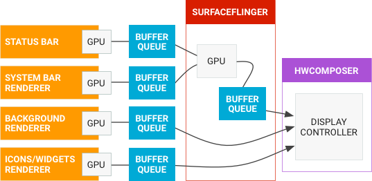
https://source.android.com/docs/core/graphics#data-flow
SurfaceFlingerが管理しているバッファキューに対して、AndroidアプリからはSurface経由で描画できるようになっている。というわけで、EGLSurface(が保持するSurface)に対してOpenGL ES で描画すると、SurfaceFlingerが画面に出力する処理をしてくれる。
App developers draw images to the screen in three ways: with Canvas, OpenGL ES, or Vulkan.
という記述がある通り、OpenGL ESを明示的に使わずにwidgetでUIを構築する場合も同じ(widgetの場合はSkiaというOpen GLをラップしたライブラリ使ってCanvasに描く)。
ということだと思う。
ここら辺はさらにドキュメントを読み漁ったり
以下の記事もとても勉強になりました。
「Androidを支える技術 Ⅰ」を読むと詳しく書いてあり勉強になります。
")
実際にAndroid端末でSurfaceを調べてみる
$ adb shell dumpsys SurfaceFlinger とコマンド実行すると、出力の最初の方に * Layer ... といくつかある。手元にあるPixel3で自分のアプリを起動した状態で、grepしつつ出力するとこうなった。
$ adb -s 8BUX1FAZ3 shell dumpsys SurfaceFlinger | grep "* Layer "
* Layer 0x72a5f7fd40 (info.bati11.android.otameshi/info.bati11.android.otameshi.MainActivity#0)
* Layer 0x72a5f57f60 (StatusBar#0)
* Layer 0x72a5f551d0 (NavigationBar0#0)
* Layer 0x72a5f412e0 (ScreenDecorOverlay#0)
* Layer 0x72a5f3e550 (ScreenDecorOverlayBottom#0)
複数のレイヤーというものがあることが分かる。 geomBufferSize もgrepの対象に追加する。
$ adb shell dumpsys SurfaceFlinger | grep -e "* Layer " -e "geomBufferSize"
* Layer 0x72a603bc60 (info.bati11.android.otameshi/info.bati11.android.otameshi.MainActivity#0)
      geomBufferSize=[0 0 1080 2160] geomContentCrop=[0 0 1080 2160] geomCrop=[0 0 -1 -1] geomBufferTransform=0
* Layer 0x72a5f57f60 (StatusBar#0)
      geomBufferSize=[0 0 1080 77] geomContentCrop=[0 0 1080 77] geomCrop=[0 0 -1 -1] geomBufferTransform=0
* Layer 0x72a5f551d0 (NavigationBar0#0)
      geomBufferSize=[0 0 1080 132] geomContentCrop=[0 0 1080 132] geomCrop=[0 0 -1 -1] geomBufferTransform=0
* Layer 0x72a5f412e0 (ScreenDecorOverlay#0)
      geomBufferSize=[0 0 1080 78] geomContentCrop=[0 0 1080 78] geomCrop=[0 0 -1 -1] geomBufferTransform=0
* Layer 0x72a5f3e550 (ScreenDecorOverlayBottom#0)
      geomBufferSize=[0 0 1080 78] geomContentCrop=[0 0 1080 78] geomCrop=[0 0 -1 -1] geomBufferTransform=0
geomBufferSizeがレイヤーのピクセル数かな?ちなみに、端末のピクセル数は以下の通り。
$ adb shell wm size
Physical size: 1080x2160
レイヤーについてドキュメントのSurfaceFlingerのページで書かれている。
SurfaceFlinger and WindowManager | Android Open Source Project
When an app comes to the foreground, it requests buffers from WindowManager. WindowManager then requests a layer from SurfaceFlinger. A layer is a combination of a surface, which contains the BufferQueue, and a SurfaceControl, which contains the layer metadata like the display frame. SurfaceFlinger creates the layer and sends it to WindowManager.
アプリがforegroundになるとWindowManagerへバッファキューの作成を依頼、WindowManagerはレイヤーをSurfaceFlingerへ依頼する。レイヤーはSurfaceとSurfaceControlの組み合わせで、WindowManagerへ送られる。
レイヤーのページもある。
Layers and displays | Android Open Source Project
どこに配置されるかやZ-orderを持っている。
つまり、Surface自身は描画自体のメモリ(バッファキュー)への参照で、レイヤーはSurface自体に加えてSurfaceへの描画が画面上のどこに配置されるかの情報を持ってる。
もうちょっと $ adb shell dumpsys SurfaceFlinger の出力を見てみる。少し下の方に行くと以下のように Displays (1 entries) 出力がある。
Displays (1 entries)
+ DisplayDevice{0, internal, primary, "Internal display"}

...

   5 Layers
  - Output Layer 0x7c2cb83680(info.bati11.android.otameshi/info.bati11.android.otameshi.MainActivity#0)
        Region visibleRegion (this=0x7c2cb83698, count=1)
    [  0,   0, 1080, 2160]
        Region visibleNonTransparentRegion (this=0x7c2cb83700, count=1)
    [  0,   0, 1080, 2160]
        Region coveredRegion (this=0x7c2cb83768, count=2)
    [  0,   0, 1080,  78]
    [  0, 2028, 1080, 2160]
        Region output visibleRegion (this=0x7c2cb837d0, count=1)
    [  0,   0, 1080, 2160]
        Region shadowRegion (this=0x7c2cb83838, count=1)
    [  0,   0,   0,   0]
      forceClientComposition=false clearClientTarget=false displayFrame=[0 0 1080 2160] sourceCrop=[0.000000 0.000000 1080.000000 2160.000000] bufferTransform=0 (0) dataspace=UNKNOWN (0) override buffer=0x0 override acquire fence=0x0 override display frame=[0 0 -1 -1] override dataspace=UNKNOWN (0) override display space=ProjectionSpace(bounds = Rect(0, 0, -1, -1), content = Rect(0, 0, -1, -1), orientation = ROTATION_0) override damage region=  Region  (this=0x7c2cb83920, count=1)
    [  0,   0,  -1,  -1]
 override visible region=  Region  (this=0x7c2cb83988, count=1)
    [  0,   0,   0,   0]
 override peekThroughLayer=0x0 override disableBackgroundBlur=false
      hwc: layer=0x0815 composition=DEVICE (2)
  - Output Layer 0x7c2cb815c0(StatusBar#0)
        Region visibleRegion (this=0x7c2cb815d8, count=1)
    [  0,   0, 1080,  77]
        Region visibleNonTransparentRegion (this=0x7c2cb81640, count=1)
    [  0,   0, 1080,  77]
        Region coveredRegion (this=0x7c2cb816a8, count=1)
    [  0,   0, 1080,  77]
        Region output visibleRegion (this=0x7c2cb81710, count=1)
    [  0,   0, 1080,  77]
        Region shadowRegion (this=0x7c2cb81778, count=1)
    [  0,   0,   0,   0]
      forceClientComposition=false clearClientTarget=true displayFrame=[0 0 1080 77] sourceCrop=[0.000000 0.000000 1080.000000 77.000000] bufferTransform=0 (0) dataspace=V0_SRGB (142671872) override buffer=0x0 override acquire fence=0x0 override display frame=[0 0 -1 -1] override dataspace=UNKNOWN (0) override display space=ProjectionSpace(bounds = Rect(0, 0, -1, -1), content = Rect(0, 0, -1, -1), orientation = ROTATION_0) override damage region=  Region  (this=0x7c2cb81860, count=1)
    [  0,   0,  -1,  -1]
 override visible region=  Region  (this=0x7c2cb818c8, count=1)
    [  0,   0,   0,   0]
 override peekThroughLayer=0x0 override disableBackgroundBlur=false
      hwc: layer=0x086 composition=DEVICE (2)
  - Output Layer 0x7c2cb8fb00(NavigationBar0#0)
        Region visibleRegion (this=0x7c2cb8fb18, count=1)
    [  0, 2028, 1080, 2160]
        Region visibleNonTransparentRegion (this=0x7c2cb8fb80, count=1)
    [  0, 2028, 1080, 2160]
        Region coveredRegion (this=0x7c2cb8fbe8, count=1)
    [  0, 2082, 1080, 2160]
        Region output visibleRegion (this=0x7c2cb8fc50, count=1)
    [  0, 2028, 1080, 2160]
        Region shadowRegion (this=0x7c2cb8fcb8, count=1)
    [  0,   0,   0,   0]
      forceClientComposition=false clearClientTarget=true displayFrame=[0 2028 1080 2160] sourceCrop=[0.000000 0.000000 1080.000000 132.000000] bufferTransform=0 (0) dataspace=V0_SRGB (142671872) override buffer=0x0 override acquire fence=0x0 override display frame=[0 0 -1 -1] override dataspace=UNKNOWN (0) override display space=ProjectionSpace(bounds = Rect(0, 0, -1, -1), content = Rect(0, 0, -1, -1), orientation = ROTATION_0) override damage region=  Region  (this=0x7c2cb8fda0, count=1)
    [  0,   0,  -1,  -1]
 override visible region=  Region  (this=0x7c2cb8fe08, count=1)
    [  0,   0,   0,   0]
 override peekThroughLayer=0x0 override disableBackgroundBlur=false
      hwc: layer=0x085 composition=DEVICE (2)
  - Output Layer 0x7c2cb88030(ScreenDecorOverlay#0)
        Region visibleRegion (this=0x7c2cb88048, count=1)
    [  0,   0, 1080,  78]
        Region visibleNonTransparentRegion (this=0x7c2cb880b0, count=1)
    [  0,   0, 1080,  78]
        Region coveredRegion (this=0x7c2cb88118, count=1)
    [  0,   0,   0,   0]
        Region output visibleRegion (this=0x7c2cb88180, count=1)
    [  0,   0, 1080,  78]
        Region shadowRegion (this=0x7c2cb881e8, count=1)
    [  0,   0,   0,   0]
      forceClientComposition=false clearClientTarget=true displayFrame=[0 0 1080 78] sourceCrop=[0.000000 0.000000 1080.000000 78.000000] bufferTransform=0 (0) dataspace=V0_SRGB (142671872) override buffer=0x0 override acquire fence=0x0 override display frame=[0 0 -1 -1] override dataspace=UNKNOWN (0) override display space=ProjectionSpace(bounds = Rect(0, 0, -1, -1), content = Rect(0, 0, -1, -1), orientation = ROTATION_0) override damage region=  Region  (this=0x7c2cb882d0, count=1)
    [  0,   0,  -1,  -1]
 override visible region=  Region  (this=0x7c2cb88338, count=1)
    [  0,   0,   0,   0]
 override peekThroughLayer=0x0 override disableBackgroundBlur=false
      hwc: layer=0x084 composition=DEVICE (2)
  - Output Layer 0x7c2cb8b150(ScreenDecorOverlayBottom#0)
        Region visibleRegion (this=0x7c2cb8b168, count=1)
    [  0, 2082, 1080, 2160]
        Region visibleNonTransparentRegion (this=0x7c2cb8b1d0, count=1)
    [  0, 2082, 1080, 2160]
        Region coveredRegion (this=0x7c2cb8b238, count=1)
    [  0,   0,   0,   0]
        Region output visibleRegion (this=0x7c2cb8b2a0, count=1)
    [  0, 2082, 1080, 2160]
        Region shadowRegion (this=0x7c2cb8b308, count=1)
    [  0,   0,   0,   0]
      forceClientComposition=false clearClientTarget=true displayFrame=[0 2082 1080 2160] sourceCrop=[0.000000 0.000000 1080.000000 78.000000] bufferTransform=0 (0) dataspace=V0_SRGB (142671872) override buffer=0x0 override acquire fence=0x0 override display frame=[0 0 -1 -1] override dataspace=UNKNOWN (0) override display space=ProjectionSpace(bounds = Rect(0, 0, -1, -1), content = Rect(0, 0, -1, -1), orientation = ROTATION_0) override damage region=  Region  (this=0x7c2cb8b3f0, count=1)
    [  0,   0,  -1,  -1]
 override visible region=  Region  (this=0x7c2cb8b458, count=1)
    [  0,   0,   0,   0]
 override peekThroughLayer=0x0 override disableBackgroundBlur=false
      hwc: layer=0x083 composition=DEVICE (2)
色々書いてあるけど、雰囲気で読むと「1つ目のOutput Layer はMainActivity で、visibleRegion(表示領域)が (0,0)~(1080,2160)、coveredRegion(他のレイヤーと重なってる領域)が (0,0)~(1080,78) と (0,2028)~(1080,2160) 」ということだろうか?(ソースコード読んで確認したのではなく、ただの予想)
2つ目と3つ目のOutput LayerはそれぞれStatusBarとNavigationBarと名前がついてるところから、画面上部と下部のエリアで、これがアプリ(MainActivity)のレイヤーと重なっている。
スクショに赤い線で分かるようにするとこんな感じ。
ScreenDecorOverlayとScreenDecorOverlayBottomはなんだろう?通知のUI出すためのスワイプのイベントやジェスチャーナビゲーションのイベント検知するための領域かなぁ?
自前アプリ内でSurfaceViewを使ってOpen GL ESで描画してみるとどうなるやってみる。アプリ内でOpen GL ES を使う場合は、SurfaceViewを用意してSurfaceを保持するSurfaceHolderを取得、SurfaceHolderを使ってEGLSurfaceを生成しOpenGL ESで描画する、というのが流れ。書いたコードはこちら↓。
動かすとこんな感じ。SurfaceView上で画像がグルグル動く。
$ adb shell dumpsys SurfaceFlinger してみる。おー! 5 Layers だったのが 6 Layers になってる。一番上に Output Layer 0x7c2cb8e270(SurfaceView というのが増えてるー。 自分で追加したSurfaceViewだ!
Displays (1 entries)
+ DisplayDevice{0, internal, primary, "Internal display"}

...

   6 Layers
  - Output Layer 0x7c2cb8e270(SurfaceView[info.bati11.android.otameshi/info.bati11.opengles.myopengles.glapp.MyOpenGlEsActivity](BLAST)#0)
        Region visibleRegion (this=0x7c2cb8e288, count=1)
    [  0,  77, 1080, 2028]
        Region visibleNonTransparentRegion (this=0x7c2cb8e2f0, count=1)
    [  0,  77, 1080, 2028]
        Region coveredRegion (this=0x7c2cb8e358, count=1)
    [  0,  77, 1080, 2028]
        Region output visibleRegion (this=0x7c2cb8e3c0, count=1)
    [  0,  77, 1080, 2028]
        Region shadowRegion (this=0x7c2cb8e428, count=1)
    [  0,   0,   0,   0]
      forceClientComposition=false clearClientTarget=false displayFrame=[0 77 1080 2028] sourceCrop=[0.000000 0.000000 1080.000000 1951.000000] bufferTransform=0 (0) dataspace=UNKNOWN (0) override buffer=0x0 override acquire fence=0x0 override display frame=[0 0 -1 -1] override dataspace=UNKNOWN (0) override display space=ProjectionSpace(bounds = Rect(0, 0, -1, -1), content = Rect(0, 0, -1, -1), orientation = ROTATION_0) override damage region=  Region  (this=0x7c2cb8e510, count=1)
    [  0,   0,  -1,  -1]
 override visible region=  Region  (this=0x7c2cb8e578, count=1)
    [  0,   0,   0,   0]
 override peekThroughLayer=0x0 override disableBackgroundBlur=false
      hwc: layer=0x0817 composition=DEVICE (2)
  - Output Layer 0x7c2cb90330(info.bati11.android.otameshi/info.bati11.opengles.myopengles.glapp.MyOpenGlEsActivity#0)
        Region visibleRegion (this=0x7c2cb90348, count=1)
    [  0,   0, 1080, 2160]
        Region visibleNonTransparentRegion (this=0x7c2cb903b0, count=2)
    [  0,   0, 1080,  77]
    [  0, 2028, 1080, 2160]
        Region coveredRegion (this=0x7c2cb90418, count=2)
    [  0,   0, 1080,  78]
    [  0, 2028, 1080, 2160]
        Region output visibleRegion (this=0x7c2cb90480, count=1)
    [  0,   0, 1080, 2160]
        Region shadowRegion (this=0x7c2cb904e8, count=1)
    [  0,   0,   0,   0]
      forceClientComposition=false clearClientTarget=false displayFrame=[0 0 1080 2160] sourceCrop=[0.000000 0.000000 1080.000000 2160.000000] bufferTransform=0 (0) dataspace=UNKNOWN (0) override buffer=0x0 override acquire fence=0x0 override display frame=[0 0 -1 -1] override dataspace=UNKNOWN (0) override display space=ProjectionSpace(bounds = Rect(0, 0, -1, -1), content = Rect(0, 0, -1, -1), orientation = ROTATION_0) override damage region=  Region  (this=0x7c2cb905d0, count=1)
    [  0,   0,  -1,  -1]
 override visible region=  Region  (this=0x7c2cb90638, count=1)
    [  0,   0,   0,   0]
 override peekThroughLayer=0x0 override disableBackgroundBlur=false
      hwc: layer=0x0816 composition=DEVICE (2)
...
SurfaceとWindowManager
ところで、adbの出力を見るとActivityのレイヤーがあることが分かる。これがアプリのUI。このレイヤーはいつできるのか?
Activityがforegroundになるとき、具体的には ActivityThread#handleResumeActivity() でViewツリーのRootとなるDecorViewが作られ、 WindowManager#addView() の引数にViewRootImplを渡してる。ここから WindowManagerImpl#addView() → WindowManagerGlobal#addView() で ViewRootImplが作られ(ViewRootImpl#mSurfaceでSurfaceを保持してる)、 ViewRootImpl#setView() が呼ばれる。ViewRootImplが保持してるSurfaceがレイヤーが持つSurfaceと同じということかなぁ?
Androidを支える技術〈I〉──60fpsを達成するモダンなGUIシステム (WEB+DB PRESS plus) の「6.5 ViewRootImpl」が参考になりました。
おしまい
WebGLでcanvasを用意してglオブジェクトを生成する部分に相当する処理は、Androidでは
- 描画対象としてEGLという仕組みというか仕様に従っている
- EGLContextとEGLSurfaceを用意してスレッドに関連づける
- Androidにおいて、EGLSurfaceが描画対象として持つのはSurface
- 結果、OpenGL ES でSurfaceに対して描画する
Surface、というか実態であるバッファーキューは複数あって、SurfaceFlingerが合成して実際の画面の描画となる。
他にも色々脱線したけど楽しい!!